- Synchronous transmission does not use start and stop bits, hence data transfer rate is quicker.
- The transmission is synchronized by speeding up at both the sending and receiving ends.
- This uses clock signals that are built at each component.
- Continual stream of data is sent between two nodes.
- Re-synchronization is one of the methods to address the lost bits.
- This method uses check digits instead of parity bits for ensuring the byte is correctly being interpreted and received.
Describe about Asynchronous Transmission.
- It uses the start and stop bits for signifying the beginning bit of ASCII character that is to be transmitted.
- For instance, ‘0100 0001 would become ‘1 0100 0001 000 1 0’’.
- The additional one bit at the beginning and ending of the transmission refers the receiver that a character is entering and the character is ended.
- When data need to be sent intermittently, this method is used.
- The start and stop bits are supposed to be opposite polarity.
- By this process, the receiver recognizes the second packet of the information that is being sent.
Explain about Common-Mode Rejection Ration.
- CMRR is used for measuring the tendency of the device that is to reject the input signals.
- These signals can be from both input leads.
- CMRR at a high level is important, as the signals of interest are represented by a small set of fluctuations of voltage.
- The voltage fluctuations are superimposed on, possibly a large voltage offset.
- Superimposition of the signals might also be done, when the information of relevance is contained in the voltage difference between the two signals.
Explain about Infinite Impulse Response.
- IIR is one of the properties of signal processing systems.
- An impulse response function that is none-zero over an infinite length of time is available in IIR systems.
- An analog filter by name RC filter is made up of a single resistor for feeding into a node.
- This is shared with a single capacitor.
- An exponential impulse response is available in this filter that is characterized by an RC time constant.
What is Impulse Response?
- Impulse Response of a system is the result that is presented with a brief input signals.
- Linear, Time-Invariant Systems are characterized by the response of their impulses.
- It is easy to analyze the systems that implements transfer functions. This is done by Laplace transform of the impulse response function.
- The output of the system can be determined in time domain by convolution of the input function with the impulse response function.
- The response of impulse and the response of Kronecker delta input are finite, as it settles zero in a finite number of interval samples.
- This process is done by Finite Impulse Response filter.
What is broadband?
- Broadband is an internet access with high speed.
- Unlike dial-up connection, broadband connection is permanently connected.
- It allows internet and telephone calls to take place simultaneously. No new land line is required.
- Modulation is done in broadband on signals to transform data better.
What is SS7?
- A global standard for telecommunications for channel signaling.
- The Common Channel Signaling System (SS7 / C7) standard defines various procedures and protocols for Public Switch Switched Telephone Network to exchange information over digital signaling network.
- Providing call control, remote network management is the primary functions of SS7.
- Controlling messages are exchanged between SS7 telephone exchanges through SS7.
- The messages are transformed from Signaling Points and SS7 Signaling Transfer Points.
What are the reasons for call drop?
A call drop occurs when
- Slips occur in media.
- There is some antenna tilting.
- Phone goes out of range.
- Electric and mechanic tilts occur.
- Signal interference occurs.
Differentiate between GSM and CDMA
GSM
- GSM uses multiple frequencies.
- Uses TDMA and FDMA for accessing signals.
- The voice rate is 9.6 KBPS.
- Uses less bandwidth.
CDMA
- CDMA uses single frequency as carrier.
- The voice rate is 14.4 KBPS.
- CDMA power control to access method is better as Phased Locked Loops are used.
- Follows soft handoff, hence call handling is more efficient.
Describe about TTCN-3.
- Testing and Test Control Notation Version 3 is one of the strongly typed tests scripting language.
- It is used testing of communicating systems conformance.
- TTCN-3 is utilized for specification of test infrastructure interfaces.
- This process is implemented with concrete communication environments.
- TTCN-3 has standardized adapter interfaces.
Radio Frequencies
Band name
Abbr
Frequency and Wavelength
Very low frequency
VLF
3–30 kHz 100 km – 10 km
Low frequency
LF
30–300 kHz 10 km – 1 km
Medium frequency
MF
300–3000 kHz 1 km – 100 m
High frequency
HF
3–30 MHz 100 m – 10 m
Difference between Radio Frequency and microwave Frequency
Microwave is the general term used to describe RFwaves that starts from UHF (Ultra High Frequency) to EHF (Extremely High Frequency) which covers allfrequencies between 300Mhz to 300GHz, lowerfrequencies are refered to as radio waves while higher frequencies are called millimeter
RF or Radio Frequency is a term that is often used to describe the number of times per second or oscillation of an electromagnet radiation. Anything between 3Hz and 300GHz is still refered to as RF waves, but they are subdivided depending on the actual frequency. Microwave is the general term used to describe RF waves that starts from UHF (Ultra High Frequency) to EHF (Extremely High Frequency) which covers all frequencies between 300Mhz to 300GHz, lower frequencies are refered to as radio waves while higher frequencies are called millimeter waves.
People have found a lot of uses for radio frequency waves, most of which are in the field of communications. Radio waves are generally used for AM/FM radio stations due to the relative ease of using these types of waves. Microwaves which occupy the upper spectrum of RF waves have an even wider range of applications. Starting from the common microwave oven that uses microwaves to heat and cook our food, to military weapons that can heat the skin of enemy forces. But the most common use of microwaves are still in communications.
The most common devices that we often use without even knowing that they are using microwaves are the WiFi routers and cards that we use to connect to our networks wirelessly. They utilize 2.4 or 5GHz RF waves to transmit data to and from our devices. Aside from that, microwave links are also used by internet service providers to transmit data from one point to another. Despite the introduction and adoption of fiber optic cables for this purpose. Microwave transmitters and receivers are still in use today in some areas. Microwaves are also being studied by some scientists today due to its capability to transmit power over the air. It is now being considered as a viable transmission method for harvesting solar power from space.
To summarize, microwave is simply a part of the RF spectrum that has become quite popular due to the large number of its possible uses.
Summary:
1. Microwave is just a subset of the RF range
2. RF covers 3 Hz to 300 GHz while Microwaves occupies the higher frequencies at 300MHz to 3GHz
3. RF waves have a lot of applications
4. RF is more commonly related to AM/FM transmission while Microwaves are used in wider applications like heating and high-bandwidth data transmission systems
5. Microwaves can also be used to transmit power from one point to another
Early internal combustion engine-poweredlocomotives and railcars used kerosene and gasoline as their fuel. Soon after Dr. Rudolf Diesel patented his first compression ignition engine in 1898, it was considered for railway propulsion.
The first electric passenger train was presented by Werner von Siemens at Berlin in 1879. The locomotivewas driven by a 2.2 kW, series-wound motor, and thetrain, consisting of the locomotive and three cars, reached a speed of 13 km/h.
Although Robert Stephenson is often credited with designing the first railway engine, Richard Trevithick ran a steam train along a short track more than 25 years before Stephenson's Rocket. .
As a mining engineer Trevithick realised that as boiler technology improved, the high pressure steam engines he was developing became not only safe but also more compact, lighter and efficient and could therefore carry their own weight plus maybe a carriage. Previous engines had been large and heavy but now they could be small enough to drive themselves along.
After experimenting on the roads for a few years, in 1804 Trevithick built the first-ever steam locomotive to run along a track – at about 5 miles an hour. It drove for nine miles, pulled five cars loaded with ten tons of iron, and had 70 ironworkers on board.
E1 Link & E1 Circuit
- details and notes about the E1 link or circuit, the most commonly used circuit within the E carrier system. Includes E1 frame and frame format.
The E1 link or circuit is probably the most commonly used format within the E carrier system. It is used for connecting a variety of elements within a network - typically small exchanges, mobile base stations and the like will use E1 circuits.
E1 Applications and standards
The E-carrier standards form part of the overall Synchronous Digital Hierarchy, SDH, scheme. This allows where groups of E1 circuits, each containing 30 circuits, to be combined to produce higher capacity. E1 to E5 are defined and there are carriers in increasing multiples of the E1 format. However in reality only E3 is widely used and this can carry 480 circuits and has an overall capacity of 34.368 Mbps.
Physically E1 line is transmitted as 32 timeslots and E3 has 512 timeslots. Unlike Internet data services which are IP based, E-carrier systems are circuit switched and permanently allocate capacity for a voice call for its entire duration. This ensures high call quality because the transmission arrives with the same latency or delay and it has the same capacity at all times. However circuit switched lines do not provide the same flexibility and efficiency that is offered by packet switched data systems.
In view of the different capacities of E1 and E3 links they are used for different applications. E1 circuits are widely used to connect to medium and large companies, to telephone exchanges. They may also be used to provide links between some exchanges. E3 lines are used where higher capacity is needed. They are often installed between exchanges, and to provide connectivity between countries.
E1 basics & E1 frame format
An E1 link or E1 line runs over two sets of wires that are normally coaxial cable and the signal itself comprises a nominal 2.4 volt signal. The signalling data rate is 2.048 Mbps full duplex and provides the full data rate in both directions.
To provide signal structure, there is a frame that has been devices. The E1 frame format has been devised to provide a frame of 32 time slots of octets, i.e. 8 bits each which are numbered 0 to 31, or as more often seen, TS0 to TS31. Obviously TS stands for Time Slot. The E1 frame repetition rate is 8000 Hz.
E1 Frame Format
The E1 frame Time Slots are nominated TS0 to TS31 and they are allocated to different purposes:
TS0: This E1 frame time slot is used for synchronisation, alarms and messages. It is reserved for framing purposes, and alternately transmits a fixed pattern. This allows the receiver to lock onto the start of each frame and match up each channel in turn. The standards allow for a full Cyclic Redundancy Check to be performed across all bits transmitted in each frame.
TS1 - TS15: These time slots are used for user data
TS16: E1 signalling data is carried on TS16. This includes control, call setup and teardown. These are accomplished using standard protocols including Channel Associated Signalling (CAS) where a set of bits is used to replicate opening and closing the circuit. Tone signalling may also be used and this is passed through on the voice circuits themselves. More recent systems use Common Channel Signalling (CCS) such as ISDN or Signalling System 7 (SS7) which sends short encoded messages containing call information such as the caller ID. Data may also be carried on this time slot.
TS17 - TS31: These E1 frame times slots are used for carrying user data
Several options are specified in the original CEPT standard for the physical transmission of data. However an option or standard known as HDB3 (High-Density Bipolar-3 zeros) is used almost exclusively.
why does we use -48 v for bts.
In earlier days of telephone networks, 48V DC was once found to be suitably high to be able to make telephone work on long telephone lines and still low enough not to cause serious danger if somebody touches the telephone wires. Telephone central offices (exchanges) so started using 48V DC. Even when newer automatic exhanges were setup, they were designed to make use of existing 48V battery sets and arrays which were available with telecom service providers. This legacy design practice has been continued and over many decades all new telecom devices have been designed to work with 48V.
The positive grounded or -48V system is also from telephone history. The negative voltage on the line was better than positive to prevent electro-chemical reactions from destroying the copper cable quickly, if cables get wet Ans- It is because of cathodic protection. It reduces the sulphation on the battery terminals.
4 G Network Architecture
Best LTE Network Architecture Diagrams
Wireless operators are rapidly expanding their LTE networks to take advantage of additional efficiency, lower latency and the ability to handle ever-increasing data traffic. RCR Wireless presents a collection of LTE network architecture diagrams.
This diagram from standards body 3GPP shows network evolution from GSM to LTE. The core technologies have moved from circuit-switching to the all-IP evolved packet core (moving left to right). Meanwhile, access has evolved from TDMA (Time Division Multiple Access) to OFDMA (Orthogonal Frequency Division Multiple Access) as the need for higher data speeds and volumes as increased.
According to Chris Pearson, president of 4G Americas, there are currently 101 commercial LTE deployments around the world. “That’s one of the fastest mobile broadband technology deployments ever,” Pearson said.
Ceragon’s diagram of basic LTE architecture demonstrates how LTE flattens network architecture. The previous Gateway GPRS support node (GGSN) for connection between the GPRS network and the Internet, and the Serving GPRS support node (SGSN) for delivery of data packets from nodes within its reach, are replaced by an all-IP structure.
Previous generations of technology relied on a “hub and spoke” design where traffic from all base stations (NodeB) was sent to the Radio Network Controller (RNC). The diagram illustrates that in LTE, the enhanced nodes (eNodeB) have direct connectivity with each other (known as x2 traffic) that enable peer-to-peer applications without reaching deep into the network.
This LTE network architecture diagram (larger version) comes from testing company Breaking Point Systems. Again, it illustrates the connection points from the end user on the left, to the evolved base stations (eNodeB) and then traffic to and between the MME and SGW (Serving Gateway), to the HSS (Home Subscriber Servier) and ultimately to the Packet Data Network (PDN) on the right.
This diagram from Juniper Networks shows the relationship of the LTE radio access network (RAN) to the LTE Evolved Packet Core/System Architecture Evolution, with the PGW (packet data network gateway) connecting the EPC to the Internet in the user/data plane, which carries users’ data traffic. Dotted lines represent network connections within the control plane.
“Once past the cell site, it’s all IP,” said Kittur Nagesh, senior director of service provider solutions for Juniper Networks. “The migration to all-IP architecture mean better spectral efficiency, and a seamless migration for both CDMA and GSM is possible with LTE. There’s also a roadmap to higher performance.”
Interphase Networks’ diagram shows the complex reality in which LTE exists, where it must interact with pre-existing network elements, including 3G networks (and small cell deployments) and Internet Multimedia Subsystems (IMS). Real-world implementations are where the complexity and differences of LTE deployments show up. The MME (Mobility Management Entity, located in the blue 4G area) authenticates wireless devices and is involved in hand-offs between LTE and previous generations of technology.
LTE-Advanced HetNet, or heterogeneous network. Image courtesy of 4G Americas.
This image from 4G Americas illustrates the future of LTE deployments, as the technology moves into later releases. A heterogeneous network, or HetNet, is a multi-layer, multi-mode, multi-band network architecture. HetNets involves the use of standard base stations (macro sites) to cover wide areas; microcells to cover individual buildings; picocells to offer wireless on the scale of separate floors of a building; and femtocells to cover small areas such as individual apartments/homes, home offices or home businesses. The goal of HetNets is to optimize spectrum use, increase network capacity and coverage, reduce capital and operating costs, and provide a consistent user experience. Future challenges for LTE HetNets include backhaul for the small cells and effective use of interference cancellation so that the various overlapping cells do not interfere with one another.
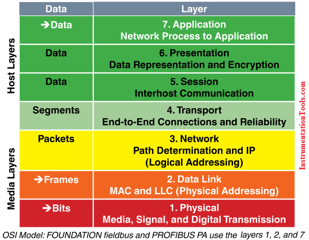
ISO/OSIModel
The International Standards Organization (ISO) has determined a general architecture of network specifications in their DIS 7498 model (applicable to most any digital network). These network specifications were developed as part of the Open Systems Interconnection (OSI) initiative to define the layering of communications in network protocol design. The OSI protocol stack is split into seven layers for modularity. All of the software layers work together, building and distributing the communications. Not all network protocols use every layer.
Digital fieldbus systems (FOUNDATION fieldbus and PROFIBUS PA) use three of the seven layers: 1, 2, and 7. This is because physical and logical layers are the same and there is no direct communication from one node to another across different segments.
TheLayersinDetail
■ Level1– Physical Layer: Defines the electrical and physical specifications for devices. In particular, the physical layer defines the relationship between a device and a physical medium. This relationship includes the layout of pins, voltages, and cable specifications.
■ Level2– Data Link Layer: Is the protocol layer that transfers data between adjacent network nodes in a wide area network or between nodes on the same segment. The Data Link Layer provides the functional and procedural means to transfer data between network entities and provides the means for error detection and correcting events that occur in the physical layer.
■ Level3–Network Layer: Establishes procedures for the encapsulation of data into packets for transmission and reception.
■ Level4– Transport Layer: Defines how complete data files are handled over a network.
■ Level5– Session Layer: Organizes data transfer in terms of the start and end of a specific transmission.
■ Level6– Presentation Layer: Defines the character sets, terminal control, and graphics commands so that abstract data can be readily encoded and decoded between communicating devices.
■ Level 7 – Application Layer: Refers to standards for generating and/or interpreting communicated data in its final form. In other words, the actual software programs used to communicate data.

 RF vs Microwave